
Butterfly Valve Symbol – Meaning, Types & Applications
A butterfly valve utilizes a rotating disc inside a pipe to rapidly begin, stop, or regulate fluid flow. Because it is extremely compact, lightweight, and affordable, it is frequently utilized for large-diameter pipelines.
In large-scale industrial plants, factories, and refineries, thousands of kilometers of pipelines carry water, oil, gas, and chemical fluids. To control the flow of these fluids, engineers utilize various kinds of industrial valves. Among them, the butterfly valve is one of the most famous options thanks to its lightweight design, compact build, and affordable nature.
But before a single pipe is laid down or a valve is installed physically, engineers should map out the whole system on paper or technical blueprints. These extremely digital drawings are renowned as Piping and Instrumentation Diagrams or procedure schematics. To stop blueprints from becoming messy with text and realistic images, every element is represented by a particular geometric drawing. Comprehending the butterfly valve symbol is crucial for any engineer, contractor, or procurement manager to make sure plants are developed safely and built without expensive mistakes.
Table of Contents
Meaning of the Butterfly Valve Symbol
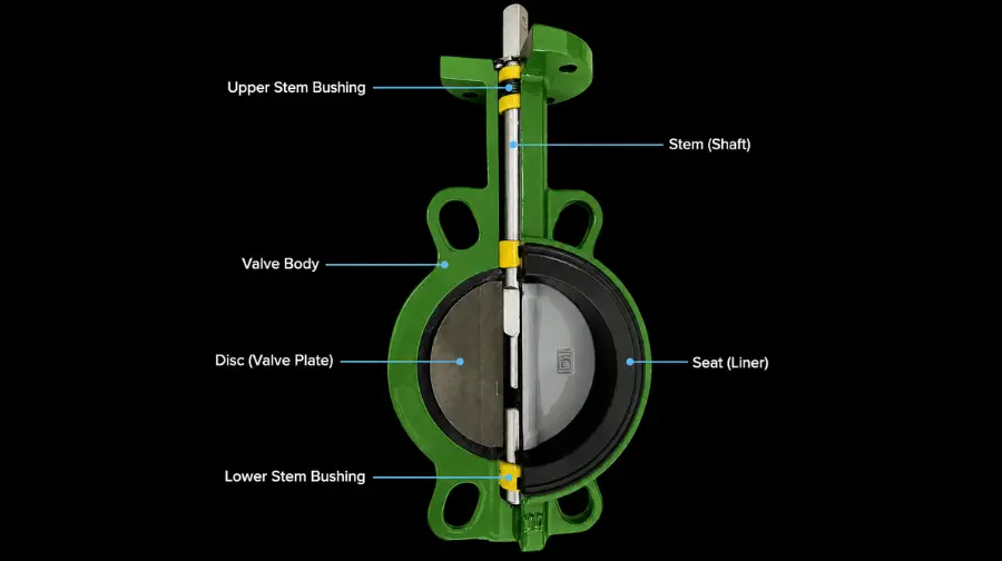
A valve symbol on an engineering schematic works as a visual code. It instantly tells the reader what type of valve is utilized, how it operates, and how it attaches to the pipeline.
The basic, common butterfly valve symbol comprises a different bowtie or two triangles meeting at a central point, as well as an intersecting line or circle.
1. The Triangles – Represent the outer valve body housing linked to the pipeline.
2. The Intersecting Line/Circle – Represents the internal circular disc that rotates on a shaft or stem to prevent or permit fluid flow.
Standardization makes sure that an engineer in Dhahran can read a schematic drafted by a designer in Houston or Tokyo without any language hurdles. The representation of butterfly valves is stringently governed by international engineering standards.
1. ISO Standards – Heavily adopted in European and international petrochemical projects.
2. ISA Standards – The core North American norm utilized for instrumentation and control design mapping.
Reading the Valve State – Open vs. Closed
On a complex engineering blueprint, a schematic not only presents that a butterfly valve exists, but it can also present its default running position or secure state utilizing line orientations and color shading.
1. Shading/Fill Conventions
- Normally Open – The common symbol is left empty or white. This presents field operators that fluid flows through this pipeline during common regular functions.
- Normally Closed – The interior triangles of the symbol are thoroughly filled in with strong black. This shows the pipeline path is closed off during normal functions.
2. Geometric Orientation
Because a butterfly valve runs on a quarter-turn principle, its open and closed positions are explicitly drawn by the internal disc line related to the horizontal pipe –
| Valve State on Drawing | Line Visual Direction | Flow Status |
| Open Position | The internal disc line is drawn parallel to the pipeline line | Unobstructed fluid passage. |
| Closed Position | The internal disc line is drawn perpendicular (at a right angle) to the pipe. | The pathway is completely sealed off. |



Types of Butterfly Valve Symbols by Actuation
A common bowtie symbol represents a generic, manual butterfly valve. However, industrial systems usually demand automated control. When mentioning how a valve is turned, designers add small graphical attachments or letters to the top of the common symbol stem.
1. Manual Actuation
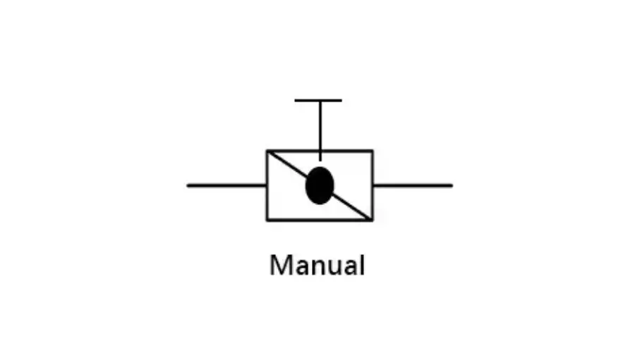
- Hand Lever/Handwheel – Presented with a small T-bar, parallel line, or loop attached to the valve stem. These are run manually by domain specialists, turning a lever or a mechanical gearbox.
2. Automated Actuation
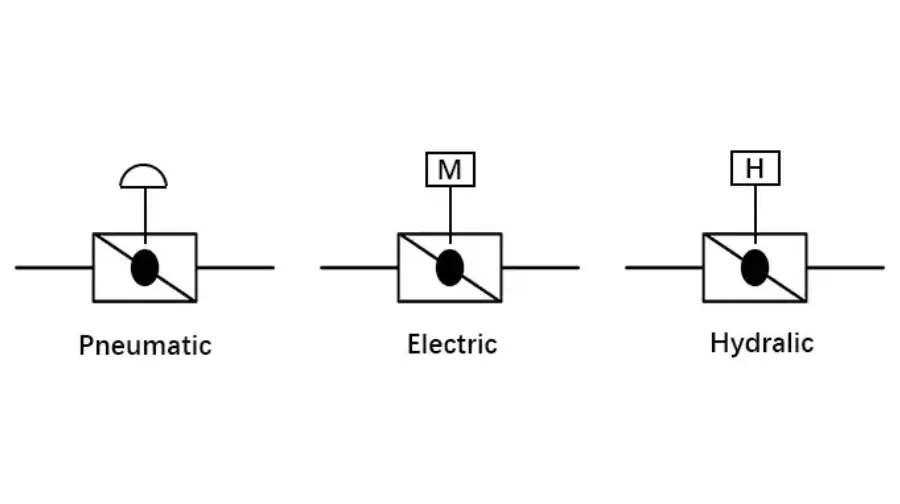
For remote functions, particularly in dangerous oil fields, valves are attached to automatic actuators. The schematic differentiates them with clear identifiers.
- Pneumatic Actuated Symbol – A small circle or box containing the letter P is attached to the stem. This means the valve opens or closes utilizing compressed air systems.
- Electric Actuated Symbol – A box with the letter E sits on top of the stem, showing it depends on electrical power networks.
- Hydraulic Actuated Symbol – Recognized by the letter H or a wavy line, which utilizes pressurized hydraulic fluid to shift positions.
End Connection Symbols – Wafer, Lug, and Flanged
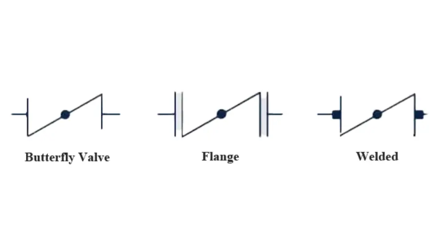
How a valve physically bolts onto a pipe matters hugely to assembly specialists and purchase groups making a Bill of Quantities. The common symbol adds minor line changes to present three primary body styles.
1. Wafer Type – Wafer butterfly valves are thin and get sandwiched directly between two common pipe flanges, utilizing long through-bolts that span throughout the valve body. On a P&ID, a wafer is kind of presented as the clean, common bowtie symbol without any additional border markings where it links to the pipelines.
2. Lug Type – Lug valves feature protruding metal threaded holes around their outer casing. This design permits bolts to screw directly into the valve body from both corners, making it perfect for end-of-line piping systems. On schematics, small circles or short perpendicular bars are added right at the contact points where the valve connects with the pipeline.
3. Double Flanged – Big, high-pressure valves usually feature integral matching flanges constructed right onto both sides of the valve body. In engineering blueprints, a double flanged valve is depicted by adding clear vertical lines matching the valve body sides, leaving a tiny gap to transparently present the bolted flange joint.
Industrial Applications of Butterfly Valves
Because they occupy minimal spatial footprints and deliver lightning-fast quarter-turn closure, butterfly valves serve crucial positions across broad industries. The versatility, longevity, and affordability of butterfly valves make them ideal for numerous butterfly valve applications in industrial systems.
1. Water Treatment and Desalination – Ruling huge volumes of sea and potable water streams seamlessly in tough facility spaces.
2. HVAC Systems – Effectively controlling airflow and temperature balances through big industrial ventilation ducts.
3. Chemical Processing – Moving non-corrosive or smoothly abrasive chemical compounds protectively utilizing soft-seated linings.
4. Oil and Gas Pipelines – Handling heavy fluid allocation networks. In significantly high-temperature and high-pressure oil fields, specialized metal-seated Triple Offset Butterfly Valves are deployed to gain zero-leakage isolation.
Engineering Overview Table
This overview table presents how distinct configurations are present from abstract P&ID blueprints to physical sector installations.
| Configuration Type | P&ID Graphical Indicator | Ideal Field Application |
| Pneumatic Wafer | Bowtie + “P” Indicator (No side flanges) | Rapid automation in low-pressure cooling or utility water lines. |
| Electric Lug | Bowtie + “E” / “M” Indicator + Lug bars | Remote process loops requiring end-of-line pipeline maintenance. |
| Manual Flanged | Bowtie + Handwheel Icon + Double parallel lines | Heavy-duty, high-diameter main lines requiring rare manual isolation. |
National Oil Groups – Your Trusted Industrial Supply Partner
Handling complicated technical blueprints, sourcing certified hardware, and deploying hefty infrastructure demands a partner with profound local knowledge and international sourcing strength. For businesses running in the Kingdom, National Oil Groups is a premier industrial supply expert and trusted Butterfly Valve Supplier in Saudi Arabia.
1. Local Deep Knowledge – Served from Headquarters in the Eastern Province, the NOS Group has deep experience with local compliance regulations, the implications of the Saudi Vision 2030 Industrial Mandates, and the rigorous quality expectations of major energy players in the area.
2. Global Sourcing Capabilities – With procurement centers located at strategic global trading locations, NOS can source elite, hard-to-find Butterfly Valves Saudi Arabia, equipment, components, and heavy-weight integrity hardware that may be challenging to obtain, quickly and easily.
3. Full Range of Supply Capabilities – The company’s capabilities are not limited to pipeline valves; they also provide engineering products and field support for the oil and gas, energy, and defense sectors to customers around the world.
4. Unwavering Commitment to Quality – Operating under the guiding principles of humility, passion, and elite craftsmanship, National Oil Groups is committed to delivering every piece of industrial hardware sourced from around the world to meet international engineering standards (e.g., API, ASME, and ISO) as it relates to design.
National Oil Groups provides the sourcing abilities to help you meet your industrial procurement needs, whether you are an EPC contractor analyzing a complex P&ID valve schematic and settling up an oil refinery or a procurement professional who requires high-quality, on-time delivery of high-performance industrial assets.
Conclusion
Knowing the schematic of an industrial piping system is just as important as the physical assembly. The Butterfly Valve Symbol is a universal language of engineering that allows design teams to communicate critical layout information from manual handwheels to sophisticated pneumatic automation without error.
Operational safety is achieved by pairing the right schematic design with certified hardware in high-stakes manufacturing environments where flow control is a must. National Oil Groups has the sourcing and logistics muscle to ensure that every blueprint symbol translates seamlessly into high-performance, field-ready Butterfly Valve Saudi Arabia equipment, especially for industrial developers working on complex infrastructure plans.
Also Read – Plug Valve vs Ball Valve: Key Differences, Advantages & Applications